Commercial & Residential Electricians in Mesa AZ.

480-434-0777

How To Wire A GFCI Outlet With Diagram For Wiring Connections

Do you have a question about wiring a GFCI outlet? You can consult with our in-office electricians in Mesa Arizona free of charge. Available Monday thru Friday, from 8:00 AM until 5:00 PM, our Mesa AZ electricians will explain how to wire a GFCI outlet and answer all of your GFCI receptacle wiring questions. Give our local Mesa electricians a call; they will save you both time and money. Free estimates are also available.

7 Steps To GFCI Outlet Wiring

Wiring a GFCI outlet diagram

Wiring a GFCI outlet is a little more complicated than wiring a regular outlet but easily learned once explained. You can learn about wiring GFCI outlets in the following 7 steps.

Note: If you are replacing an existing GFCI outlet with a new GFCI outlet we suggest that you read our page about replacing a GFCI outlet.

Information symbol

Tools Needed:

  • Flashlight
  • Phillips Head Screwdriver
  • Slotted Screwdriver
  • Wire strippers
  • Voltage Tester

Materials Needed:

  • GFCI Outlet
  • Outlet Cover
  • Wire Nuts
  • Roll Of Electrical Tape

Step 1. Turn The Circuit Breaker Off:

  • At the circuit breaker box or fuse box, turn off the electrical power.
  • Confirm that the power is shut off with a voltage tester. Do not depend on the circuit breaker labels. Over time the wiring in the panel may have been changed leaving the breakers mislabeled.
  • Remove the finish plate from the outlet.

Step 2. Take The Existing Receptacle Out Of The Electrical Box:

  • Remove the 2 mounting screws that are securing the existing electrical outlet and pull it all the way out of the box.
  • Disconnect the attached wires on the existing electrical outlet from the terminal screws. (If the wires are reasonably long, you can cut them off close to the outlet)

Step 3. Prepare The Wires So They Can Be Reconnected To The New GFCI Outlet:

  • Cut the ends off the wiring (the previously connected portion) and straighten them.
  • Strip off about ¾ of an inch of insulation from each conductor for the new wiring connections.

Step 4. Separate And Identify The Line Side Wires:

Note: If only 1 black, 1 white and 1 green or bare wire are present in the electrical outlet box you can skip past this wiring step.

  • Pull the conductors out of the electrical box and separate all black and white conductors so no one wire can contact another.
  • Your green or bare conductors can and should remain spliced together.
  • Turn the power back on and using your voltage tester, carefully touch the black probe to the ground wire.
  • Using the red probe on your voltage tester, touch each black conductor until you find the live one. This is the line side hot wire and it will get attach on the line side brass terminal screw on your new GFCI outlet.
  • Keeping the red probe in contact with the identified hot black conductor, remove the other probe from the ground and touch each individual white conductor until voltage is detected again. This will be the line side white conductor and it will get attached on the line side silver terminal screw on your new GFCI outlet.
  • Carefully cap off the ends of each individual line side conductor with a yellow wire nut. Do not put any wires together, the power is still on!
  • Turn all electrical power off again and confirm that the wiring has no power before proceeding.

Step 5. Terminate The Conductors Using The How To Wiring Diagrams Below:

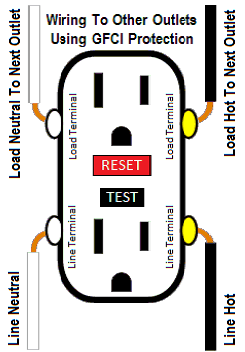
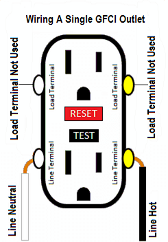
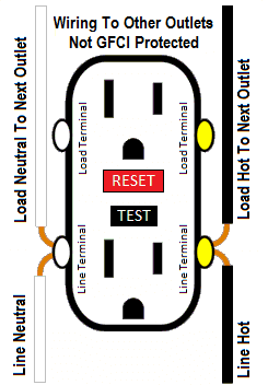
Your GFCI outlet can be used different ways. Refer to these diagram about wiring GFCI receptacles:

GFCI protection is provided at the GFCI outlet and to other ordinary outlets.

Diagram about wiring your GFCI outlet's load side terminals to other outlets with ground fault protection connected
  • Terminate the black line side wire (the black wire with the yellow wire nut) on the brass line side screw.
  • Terminate the white line side wire (the white wire with the yellow wire nut) on the silver line side screw.
  • Terminate the remaining black load side wires on the brass load side screw.
  • Terminate the remaining white load side wires on the silver load side screw.
  • Terminate the bare or green wire to the ground screw.

GFCI protection is provided only at the GFCI outlet.

Diagram demonstrating how to wire a single GFCI outlet
  • Terminate the black line side wire (the black wire with the yellow wire nut) on the brass line side screw.
  • Terminate the white line side wire (the white wire with the yellow wire nut) on the silver line side screw.
  • Terminate the bare or green wire to the ground screw.
  • The brass and silver load side screws are not used.

GFCI protection is only at the GFCI outlet and ordinary outlets are not GFCI protected.

Diagram demonstrating how to wire your GFCI outlet to other outlets without GFCI protection hooked up
  • Terminate all black wires on the brass line side screw.
  • Terminate all white wires on the silver line side screw.
  • Terminate the bare or green wire to the ground screw.
  • The brass and silver load side screws are not used.
Information symbol
  • Line and load will be clearly labeled on the back of the GFCI outlet. Often times the load side wiring terminals of the GFCI receptacle will be covered with a piece of tape.
  • Some GFCI outlets will have compression plates where a straight wire can be inserted into the back and others will require the conductor to be bent into a “J-hook” and wrapped around the terminal screw. When wrapping the hook around the screw make sure the end of the hook is going clockwise. Doing this will pull the hook closed around the screw as the screw gets tightened.

Step 6. Insert The New Receptacle Into The Electrical Box:

  • Fold the ground conductor into the electrical box first. It is best to try to position the ground furthest back in the box to avoid any unintentional short circuiting to the terminal screws.
  • Next, fold the white and black conductors into the box. Try to keep the white conductors on the side of the box where the silver screws of the outlet will be and the black conductors on the brass screw side of the box. This will keep the wiring from crossing behind the outlet and leave you with more space for the GFCI outlet.
  • Insert the GFCI outlet completely into the electrical box and tighten down the mounting screws.
  • Attach the finish cover plate.
Warning symbol
  • For added protection, you can wrap the sides of the GFCI outlet with electrical tape to cover the terminal screws. This is a good idea, especially if there is a lot of wiring and not much room in the box.
  • When attaching the cover plate, leave the screw slots in a vertical position. This is important in bathrooms and exterior locations. We want all moisture to fall freely through the slot to avoid rusting.

Step 7. Turn All Of The Electricity Back On At The Circuit Breaker:

Turn your circuit breakers back on. This should restore electrical power to the new GFCI outlet but it will not work until the reset button is pushed.

  • Note: If the circuit breaker won’t reset or trips, it indicates a problem with the line side wiring behind the outlet. Double check steps 5 and 6 and inspect the line side black conductor for damage.

Press the reset button to activate the outlet.

  • Note: If the reset button will not reset make sure the line and load wiring is terminated properly as described in step 5. Also inspect the load side black and white conductors for damage and make sure the ground conductor is not coming into contact with any other screws on the GFCI outlet.
Information symbol

About Wiring A GFCI Outlet To Line And Load

The back of all GFCI outlets are clearly marked line and load. It is important to know which is which before beginning. They usually come from the factory with a piece of tape covering the load connection points for further identification. Refer to the attached diagrams above about how to wire GFCI outlets for clarity or contact our in-office electrician in Mesa AZ free of charge.

How To Connect The Line Side Of A GFCI Outlet:

The line terminals of a GFCI outlet connect to the power supply conductors that are connect at the circuit breaker or fuse box. Line essentially means supply. The line conductors are the incoming hot conductors. In most residential applications a Romex cable will be used which will include a bare (ground), white (neutral) and black (hot) conductor. GFCI outlet requirements mandate that line terminals identified by color require the white line conductor (neutral) to connect to the silver line terminal and the black line conductor (hot) to connect to the brass line terminal.

How To Connect The Load Side Of A GFCI Outlet:

The load terminals of a GFCI outlet can be used to connect additional outlets to the same GFCI protected power. Load essentially means using the protected power (opposed to supplying the power). Load terminals identified by color require the white load conductor or conductors to connect to the silver load terminal and the black load conductor or conductors to connect to the brass load terminal.

Ground fault circuit interrupters (GFCI’s) implement line and load connections to employ an automatic trip action when a difference of electricity is detected. This is why it is imperative to put the correct conductors on the correct screws of the GFCI receptacle. If any of the wiring is not correctly connected to the right screw, the GFCI outlet will not work.

Visit us at tips for common electrical problems in houses for additional help.

Dolce Electric Co has been voted best electricians Mesa AZ and would be proud to earn your vote too. We schedule an electrician Mesa AZ homeowners and businesses can call for electrical help Monday thru Friday, during office hours. Our in-office electrician has over 30 years of experience as a journeyman electrician and is sure to be able to help you will any electrical wiring issue that you are experiencing. Give us a call; you will be happy you did!